Introduction: The Hidden World of Tissue Stiffness and the Limitations of Conventional Ultrasound
Imagine being able to see not just the shape and structure of your internal organs, but also feel their texture—distinguishing a soft, healthy liver from a hardened, diseased one; or identifying a malignant tumor nestled within bone, invisible to standard imaging. This is the promise of elastography, a revolutionary branch of medical imaging that maps the mechanical properties, specifically the stiffness or elasticity, of biological tissues. While conventional B-mode ultrasound excels at visualizing anatomy, it fundamentally lacks the ability to differentiate tissues based on their biomechanical characteristics. This limitation becomes critically important in fields like oncology, where cancerous lesions are often stiffer than surrounding healthy tissue, and in orthopedics, where assessing bone health or detecting fractures requires penetrating materials with vastly different acoustic properties.
For decades, researchers have sought solutions to this problem. Techniques like strain elastography, which involves manually squeezing tissue and measuring the resulting deformation, offer real-time feedback but suffer from significant drawbacks: they are highly operator-dependent, subjective, and struggle with deep-tissue imaging. Enter a novel approach rooted in the fascinating physics of nonlinear acoustics: Difference-Frequency Ultrasound (dfUS). This technique leverages the interaction of two high-frequency sound waves to generate a third, lower-frequency signal whose strength is directly proportional to the tissue’s inherent nonlinearity—a property intrinsically linked to its elasticity. While promising, previous dfUS systems were cumbersome, relying on multiple separate transducers that required complex mechanical scanning, making them impractical for clinical use.
This article delves into a groundbreaking advancement detailed in a recent study published in Medical Image Analysis. Researchers have developed a compact, programmable transmit scheme using a single 2D array probe to generate dfUS signals electronically. This innovation overcomes the bulk and complexity of past systems, paving the way for portable, high-resolution elastographic imaging capable of penetrating challenging materials like bone and providing unprecedented contrast for detecting subtle changes in tissue stiffness. We will explore the science behind dfUS, the ingenious engineering of this new array-based system, its impressive performance metrics compared to traditional ultrasound, and its profound implications for future diagnostic medicine.
The Science Behind the Signal: Understanding Nonlinear Acoustics and dfUS
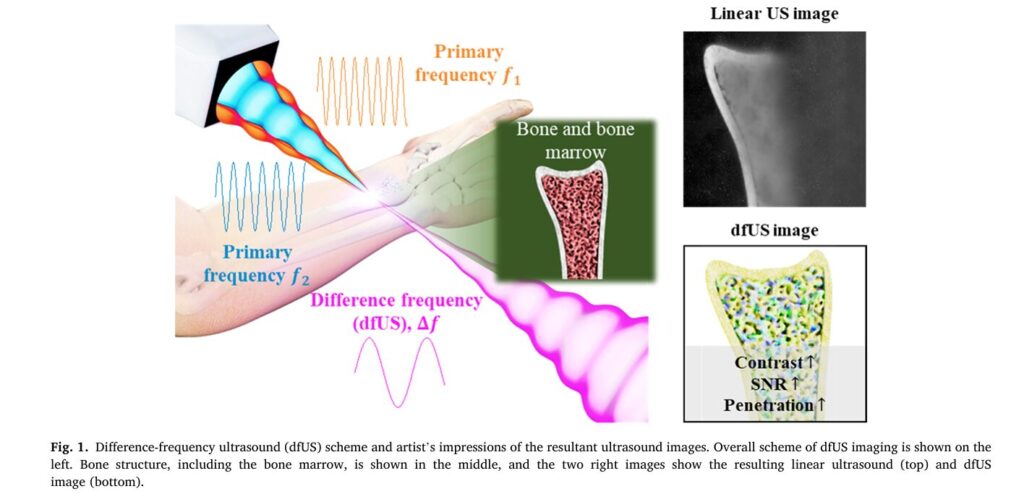
To appreciate the significance of this new technology, we must first understand the fundamental principles of difference-frequency ultrasound. At its core, dfUS exploits a phenomenon known as nonlinear wave interaction. When two intense ultrasound waves, each with a distinct primary frequency (ωa and ωb), propagate through a medium, they don’t simply pass through each other unchanged. Instead, they interact in a nonlinear fashion, generating new frequencies. One of these newly generated frequencies is the difference frequency (ω_-), calculated as:
This interaction, historically referred to as “scattering of sound by sound” or the “parametric effect,” is governed by the medium’s coefficient of nonlinearity, denoted by β. This coefficient is a material property that quantifies how the medium responds to intense acoustic pressure. It is mathematically related to the more commonly referenced parameter B/A, where β = 1 + B/(2A). Crucially, different biological tissues exhibit different B/A values. For example, fat, muscle, and tumor tissue all have unique nonlinear parameters. Therefore, by measuring the amplitude of the difference-frequency signal, scientists can indirectly map the spatial distribution of β within a tissue, effectively creating an image of its elasticity—a true elastographic contrast image.
The mathematical relationship governing the amplitude of the difference-frequency signal (p_-) is given by:
Where:
p_-is the acoustic pressure of the difference-frequency signal.βis the coefficient of nonlinearity.p0aandp0bare the maximum pressures of the two primary-frequency waves.ρ0is the ambient density of the medium (e.g., water or tissue).c0is the speed of sound in the medium.xis the spatial variable (distance along the propagation path).τ = t - x/c0is the retarded time.ω_-is the angular difference frequency.
From this equation, we can derive a formula to calculate β if we know the other variables:
In practice, for imaging, the key insight is that the difference-frequency signal amplitude p_- is proportional to the product of the primary signal amplitudes (p0a, p0b) and the local value of β. By normalizing the measured p_- by p0a, p0b and scanning across a region, a quantitative map of β can be constructed. This normalized value, often represented as γΔf, normalized, forms the basis of the final elastographic image.
Why dfUS Over Traditional Methods?
- High Contrast for Stiffness: Unlike linear ultrasound, which relies on impedance mismatches (reflections at boundaries), dfUS generates a signal based on the intrinsic nonlinear properties of the material itself. This provides a direct, high-contrast measure of tissue elasticity.
- Penetration of High-Impedance Materials: Conventional ultrasound struggles to image through bones or air-filled cavities because of massive acoustic impedance mismatches, which cause almost total reflection of the sound wave. dfUS, however, can penetrate these barriers. The difference-frequency signal is generated within the tissue where the two primary beams intersect, allowing imaging of structures like bone marrow or tumors embedded in bone, which was previously only possible with expensive or harmful modalities like MRI or X-ray CT.
- Quantitative Potential: The direct link between signal amplitude and the
B/Aparameter offers a pathway towards truly quantitative elastography, moving beyond qualitative “soft vs. hard” assessments.
Engineering Breakthrough: Designing a Compact, Programmable dfUS Array
The major hurdle for dfUS has always been the hardware. Previous systems relied on three separate transducers: two for transmitting the primary frequencies and a third, often a sensitive hydrophone, for receiving the much weaker difference-frequency signal. This setup was bulky, expensive, difficult to calibrate, and incapable of electronic beam steering, requiring slow, mechanical scanning.
The research team’s solution is elegantly simple yet profoundly innovative: integrate the transmission functionality of the two primary-frequency transducers into a single, commercially available 2D matrix array probe.
The Core Innovation: A Reconfigured Ring Array
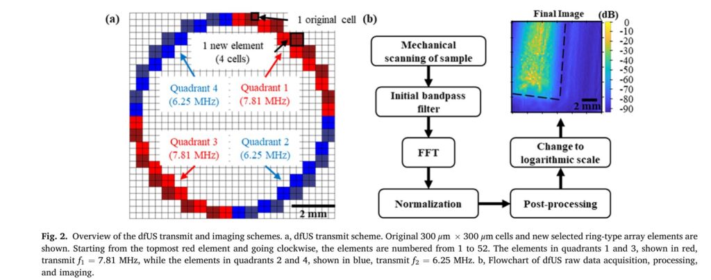
The researchers used a standard 32×32 2D matrix array probe with a center frequency of 7.5 MHz. Instead of using all 1024 elements independently, they grouped four adjacent 300×300 μm cells to form a single, larger element. From these newly formed elements, they selected 52 to create a ring-shaped array. This ring was then divided into four quadrants, each containing 13 elements.
- Quadrant 1 & 3 (Red): Transmit the first primary frequency (
f1 = 7.81 MHz). - Quadrant 2 & 4 (Blue): Transmit the second primary frequency (
f2 = 6.25 MHz).
By firing these opposing quadrants simultaneously, the two primary-frequency beams intersect within the tissue, generating the desired difference-frequency signal (Δf = f1 - f2 = 1.56 MHz). This configuration is highly customizable. The Vantage 64 ultrasound research system allows individual control of each of the 52 elements, meaning the firing pattern isn’t limited to alternating quadrants. Elements could be programmed to fire at different user-defined frequencies or patterns to optimize the intersection zone for specific applications.
Key Advantages of the Array-Based Scheme:
- Electronic Steering and Focusing: This is perhaps the most significant advantage. Unlike confocal transducers or multi-transducer setups, this array can electronically steer and focus the ultrasound beams in the X, Y, and Z directions using software. This eliminates the need for mechanical movement, enabling rapid, precise, and automated scanning. As demonstrated in the study, the focal point could be adjusted electronically from 23 mm to 33 mm without physically moving the probe.
- Compactness and Simplicity: Integrating the two primary transmitters into one probe drastically reduces the size, weight, and complexity of the overall system, making it far more suitable for clinical environments.
- Programmability: The system is fully programmable, allowing researchers to experiment with different frequencies, pulse lengths, and firing patterns to optimize performance for various targets.
- Safety: The system operates at a very low mechanical index (MI) of 0.0248, well below the FDA-mandated safety limit of 1.9, making it safe for human use. This low MI also suggests room for future improvement; increasing the transmit power could significantly boost image quality.
Performance Validation: Quantifying the Superiority of dfUS Imaging
The true test of any new imaging technology lies in its performance. The researchers conducted a series of rigorous experiments to validate their system and compare dfUS against conventional linear ultrasound. The results were striking, demonstrating clear advantages in signal-to-noise ratio, sensitivity, and contrast.
Experiment 1: Penetrating High-Acoustic-Impedance Targets (Chicken Bone)
The team created a phantom by embedding a piece of chicken bone (a high-acoustic-impedance material) in a 1% agarose gel. They acquired both linear ultrasound and dfUS images with the focus set at 25 mm.
- Contrast: The dfUS image exhibited a dynamic range of 94.1 dB, compared to just 21.9 dB for the linear ultrasound image. This represents a remarkable 72.2 dB increase in contrast. Visually, the dfUS image clearly resolved the cortical bone and the softer bone marrow, while the linear ultrasound image showed poor differentiation.
- Signal-to-Noise Ratio (SNR): Calculated from regions of interest, the dfUS SNR was consistently higher than the linear ultrasound SNR across various depths (24-25 mm). The average SNR gain was 14.8 dB, equivalent to a 5.51-fold improvement. This means the useful signal is much stronger relative to background noise, leading to clearer, more reliable images.
- Sensitivity to Small Elasticity Changes: In another experiment, four circular agarose targets with varying concentrations (1.5%, 2%, 2.5%, 3%) were placed on a 1% agarose base. Agarose concentration correlates with stiffness. Linear ultrasound struggled to differentiate between the targets, especially at lower concentrations. dfUS, however, showed a clear gradient in signal intensity corresponding to the increasing stiffness. Statistical analysis revealed that the slope of the linear fit for dfUS data was 58.5% higher than for linear ultrasound data, indicating significantly greater sensitivity to small changes in tissue elasticity.
Experiment 2: Performance Metrics Summary Table
| Performance Metric | Linear Ultrasound | Difference-Frequency Ultrasound (dfUS) | Improvement Factor |
|---|---|---|---|
| Signal-to-Noise Ratio (SNR) | Baseline | +14.8 dB | 5.51x |
| Sensitivity (Slope of Elasticity Fit) | Baseline | +58.5% | 1.585x |
| Contrast (Dynamic Range) | Baseline | +74.8 dB | ~5500x |
(Note: The 74.8 dB figure is an average across multiple biological target experiments, including the chicken bone and agarose phantoms.)
These numbers are not just abstract statistics; they translate directly into clinical benefits. A 74.8 dB increase in contrast means structures that were previously indistinguishable become sharply defined. A 14.8 dB SNR gain means images are less grainy and artifacts are reduced. A 58.5% increase in sensitivity means the system can detect smaller, earlier-stage pathological changes in tissue stiffness, potentially leading to earlier diagnosis of diseases like cancer or fibrosis.
Technical Challenges and Limitations:
While the results are impressive, the study acknowledges several limitations stemming from the use of a commercial probe with limited bandwidth (approximately 38% at -3 dB).
- Frequency Discrepancy: The actual transmitted frequencies deviated from the intended values. To compensate, the team used long 20-period pulses instead of single-cycle pulses. While effective for generating a strong difference-frequency signal, this sacrifices axial resolution, which is less critical for the 2D imaging performed in this study but would be a factor for 3D volumetric imaging.
- Single-Ring Array Limitation: A perfect ring array cannot focus along its central axis (Z-axis) unless the X or Y coordinates are non-zero, creating a potential blind spot. An annular array with concentric rings would be needed for full 3D focusing control.
- External Hydrophone: Due to the probe’s limited bandwidth, the difference-frequency signal had to be detected by a separate hydrophone, rather than integrated into the same probe for reflection-mode imaging. This is a temporary workaround.
Future Directions: Towards Integrated, Clinical-Grade dfUS Systems
The success of this programmable array-based dfUS system is a significant milestone, but it is viewed by the researchers as a crucial step towards even more advanced and practical clinical tools. Several exciting avenues for future development are outlined in the paper.
1. Integration of Transmission and Reception: The ultimate goal is to eliminate the external hydrophone. Future iterations aim to integrate the reception capability for the difference-frequency signal directly into the same 2D array probe. This would allow the system to operate in reflection mode, similar to conventional ultrasound, where the same probe both transmits and receives signals. This integration would dramatically enhance the system’s compactness, reduce cost, and make it truly portable for bedside or point-of-care use.
2. Advanced Array Designs: Moving beyond the single-ring design, the next logical step is to develop an annular array composed of multiple concentric rings. Each ring could be dedicated to transmitting one of the primary frequencies, or even to receiving the difference-frequency signal. This configuration would provide superior control over beamforming and focusing in all three dimensions, eliminating the blind spot issue and enabling true 3D elastographic imaging.
3. Wide-Bandwidth Transducers: The current system’s performance is constrained by the narrow bandwidth of the piezoelectric transducer. Future work will explore the use of wide-bandwidth transducers, such as capacitive micromachined ultrasonic transducers (CMUTs). CMUTs offer superior bandwidth and performance compared to conventional probes, which would allow for shorter pulses (improving axial resolution) and stronger, cleaner difference-frequency signals without the need for long, compensatory pulses.
4. Optimizing for Clinical Use: The current system uses a very low mechanical index for safety. Future versions can safely employ higher transmit powers, leveraging the full potential of the wide-bandwidth transducers to further improve image quality, penetration depth, and frame rate. Research will also focus on optimizing the intersection angle of the primary beams (currently limited to ~20° due to aperture size) to maximize spatial resolution, although the authors note that achieving optimal angles (e.g., 90°) might compromise portability.
Conclusion: A New Era of High-Contrast, Portable Elastography is Dawning
The development of a compact, programmable, array-based transmit scheme for difference-frequency ultrasound represents a transformative leap forward in medical imaging technology. By overcoming the historical limitations of bulkiness, complexity, and lack of electronic steering, this innovation brings the powerful capabilities of dfUS—high-contrast elastography and the ability to image through high-acoustic-impedance materials like bone—within reach of practical clinical application.
The experimental results are unequivocal: dfUS outperforms conventional linear ultrasound by a staggering margin. With a 14.8 dB higher signal-to-noise ratio, 58.5% improved sensitivity to small elasticity changes, and a 74.8 dB greater contrast, this technology promises to reveal anatomical and pathological details previously hidden from view. Imagine a future where radiologists can instantly visualize the stiffness of a suspicious breast lesion, neurosurgeons can map nerve stiffness during surgery, or orthopedists can assess bone microstructure and fracture risk without resorting to ionizing radiation.
While challenges remain, particularly regarding transducer bandwidth and full system integration, the foundational work presented here provides a clear roadmap for the future. The transition from a laboratory prototype to a clinically viable tool is now a tangible possibility. As researchers continue to refine the technology—integrating reception, adopting wider-bandwidth transducers, and developing sophisticated annular arrays—the dream of portable, high-resolution, quantitative elastography for a vast array of medical conditions moves closer to reality.
Call to Action: What’s Next for You?
This breakthrough in ultrasound imaging opens up exciting possibilities for clinicians, researchers, and patients alike. If you’re involved in medical imaging, oncology, orthopedics, or biomedical engineering, consider the following:
- Clinicians: Stay informed about the progress of dfUS technology. Discuss its potential applications with your department’s radiology or research teams. Could this technology address a specific diagnostic challenge you face daily?
- Researchers: Explore collaborations with the authors or institutions working on dfUS. Consider how this technology could be applied to your specific area of study, whether it’s characterizing tumor microenvironments, monitoring tissue regeneration, or developing new biomarkers.
- Patients and Advocates: Educate yourself about the advancements in medical imaging. Ask your healthcare providers about the latest technologies available for diagnosis and monitoring. Your awareness can help drive demand for innovative, safer, and more effective diagnostic tools.
- If you want read the full paper, then click this link.
The journey from theoretical physics to clinical practice is often long, but this study marks a pivotal moment. The potential to see the unseen—to quantify the texture of our tissues—is no longer science fiction. It is the next frontier in diagnostic medicine, and it is being built, one programmable array element at a time. Share your thoughts on the future of elastography in the comments below, or connect with us to learn more about how this technology might impact your field.
Related posts, You May like to read
- 7 Shocking Truths About Knowledge Distillation: The Good, The Bad, and The Breakthrough (SAKD)
- MOSEv2: The Game-Changing Video Object Segmentation Dataset for Real-World AI Applications
- MedDINOv3: Revolutionizing Medical Image Segmentation with Adaptable Vision Foundation Models
- SurgeNetXL: Revolutionizing Surgical Computer Vision with Self-Supervised Learning
- How AI is Learning to Think Before it Segments: Understanding Seg-Zero’s Reasoning-Driven Image Analysis
- SegTrans: The Breakthrough Framework That Makes AI Segmentation Models Vulnerable to Transfer Attacks
- Universal Text-Driven Medical Image Segmentation: How MedCLIP-SAMv2 Revolutionizes Diagnostic AI
- Towards Trustworthy Breast Tumor Segmentation in Ultrasound Using AI Uncertainty
- DVIS++: The Game-Changing Decoupled Framework Revolutionizing Universal Video Segmentation
- Radar Gait Recognition Using Swin Transformers: Beyond Video Surveillance
Downloaded the indibetapk the other day Smooth as butter on my phone Got a decent win on the cricket Loving it indibetapk