
Key points
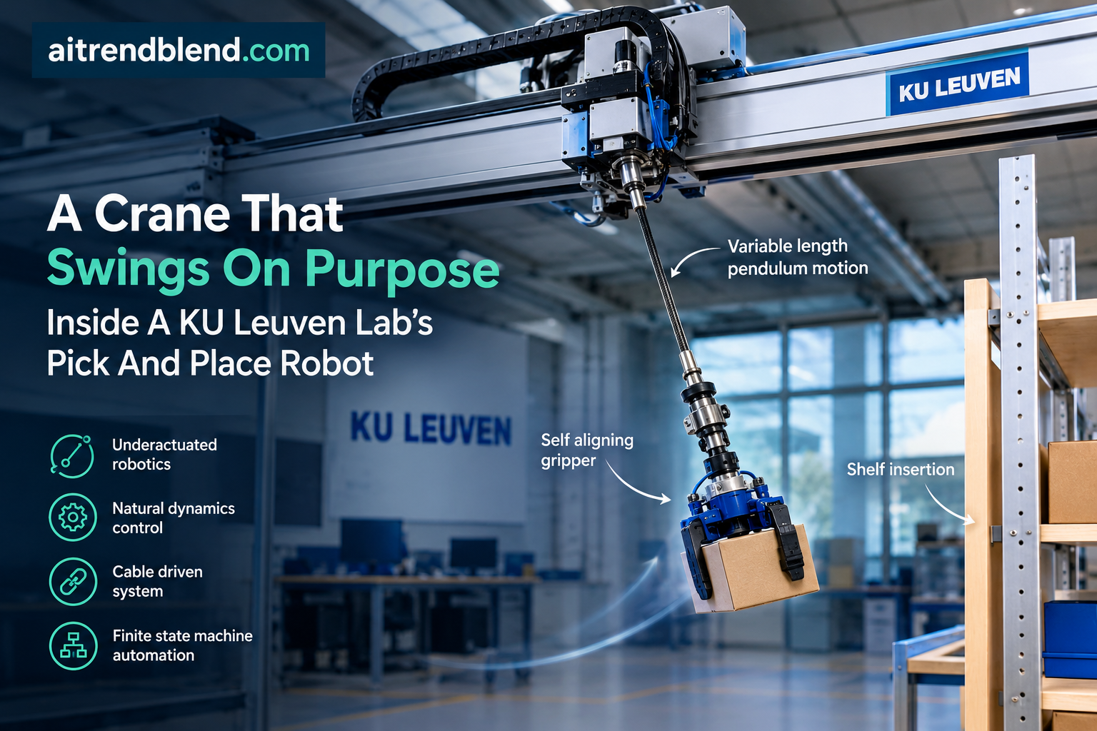
- A gantry crane can only control the three positional degrees of freedom of its payload and is underactuated in all three rotations, which normally makes precise grasping difficult and limits the workspace to positions reachable from directly above.
- The team solved the orientation problem with a passively self aligning gripper shaped so an ordinary horizontal push from the crane mechanically rotates it into the correct grasping angle, with no extra motors or sensors.
- They solved the reach problem with a controlled swinging motion, modeled as a variable length pendulum whose cable length changes deliberately, letting the payload be inserted into a shelf that is blocked from above.
- Across 48 grasping trials spanning 16 payload orientations, the gripper caught the handle on the first attempt 47 times, and a monitoring system caught and recovered from every deliberately induced failure.
- The authors are unusually candid that one of their five core modeling assumptions, that the hoist motor tracks a commanded velocity fast enough to ignore, breaks down during exactly the maneuver the paper is built around, and they explain precisely why.
Warehouses and construction sites are full of tasks that do not need a surgeon’s precision the whole way through. Unloading a truck, stacking pallets, moving crates across a yard, all of these only really need accuracy at the very start, when you grab the object, and at the very end, when you set it down. Everything in between can be sloppy. Humans exploit that gap constantly, letting a heavy box swing and guiding it into place rather than fighting its momentum the entire time. Industrial robotics mostly does not, because the standard toolkit, a stiff jointed arm precisely tracking a preplanned path, is built around the opposite assumption, that every point along the trajectory matters equally.
Boris Deroo, Erwin Aertbeliën, Wilm Decré, and Herman Bruyninckx, all associated with the Department of Mechanical Engineering at KU Leuven, built a robot around the human approach instead. Their platform is a gantry crane, the kind of overhead rail system that moves a hoist along X and Y axes and lowers a cable on the Z axis, and it deliberately embraces the crane’s two weaknesses rather than engineering around them.
Why a crane is the wrong tool and the right tool at the same time
A conventional serial robot arm with five to seven joints can, in principle, place an object at any position and any orientation. That flexibility costs weight. The authors point out that robot mass scales roughly linearly with rated payload once you design for the stiffness that precise trajectory tracking demands, comparing the highest payload to weight ratio models across major manufacturer lineups. Heavier robots cost more, use more energy, and are more dangerous in a collision.
A gantry crane sidesteps that tradeoff almost by accident. Because the payload hangs from a cable, the moving mass the motors actually have to accelerate is small, and any collision transfers only the payload’s own energy into whatever it hits rather than the robot’s structural mass as well. The catch is right there in the name, it is a crane. It can position the payload in three dimensional space but it cannot directly control the payload’s orientation at all. Whatever angle the object settles into as it hangs from the hook is the angle you get. And because most crane control strategies keep the payload nearly still to avoid dangerous swinging, the reachable workspace is normally limited to positions you can get to by moving mostly straight down from above.
Fixing the rotation problem with geometry, not electronics
The first contribution is almost stubbornly simple once you see it. Instead of adding a wrist motor to control the gripper’s yaw, the researchers designed the gripper’s physical surface so that a sideways push from the crane makes it rotate itself into the correct orientation, using nothing but contact mechanics.
Here is the underlying logic. When the crane is used quasi statically, meaning it moves slowly enough that the payload is not swinging, the gripper’s center of mass naturally hangs in line with the cable, which pins down two of the three rotational degrees of freedom automatically. Only the yaw, the rotation around the cable’s own axis, is left undetermined. The team’s insight was that this single remaining degree of freedom could be resolved mechanically rather than electronically. They shaped the inside surface of the hook so that, when it makes contact with the crate’s handle and the crane keeps pushing horizontally, every possible contact point produces a rotational moment that points toward one specific stable configuration and no other.
The physics behind that claim is a stability argument. As long as every point on the gripper surface currently touching the handle sits on the same side of the applied horizontal force, a turning moment gets induced, and only the fully aligned position is a genuine stable equilibrium. There is technically one unstable equilibrium point directly opposite the desired orientation, the kind of knife edge balance that would in theory let the gripper get stuck backwards, but the authors note plainly that real world vibration and disturbance make actually landing on that exact point essentially impossible in practice.
Getting this right required real design tradeoffs, not just a clever idea. The distance from the cable attachment point to the contact surface controls the lever arm of the self aligning torque, so a longer distance rotates the gripper more decisively, but it also makes the whole gripper bulkier and harder to maneuver around the payload. The team settled these tradeoffs specifically for grasping a handled beer crate, even wedging the bottom of the gripper so that if it lands wrong inside the crate it cannot balance on a bottle top, it has to topple and fall between the bottles instead of getting stuck.
Fixing the reach problem by controlling a fall instead of preventing one
The second contribution addresses the workspace limit, and this is where the physics gets genuinely interesting. The team categorizes robotic dynamic motions into three levels of increasing difficulty, built around the idea of a static workspace, defined as any position where the robot could hold the payload steady indefinitely. Level one dynamic motions stay entirely inside that safe zone and just move faster. Level two motions leave the static workspace but the system stays observable the whole time, so errors can at least be seen even if they cannot always be corrected. Level three, the hardest category, leaves the static workspace and loses observability during part of the motion too, meaning the controller is temporarily flying blind with no way to check whether anything has gone wrong.
Placing a crate on a shelf that is blocked from directly above is a level three problem, because once the cable slides under the shelf’s edge, the camera looking straight down from the hoist can no longer see the tracker marking the end effector’s position. The paper’s whole shelf insertion demonstration deliberately tackles the hardest category on its own difficulty scale, rather than a safer level one or two case.
The physics of a pendulum that changes length
The model underneath all of this is a variable length pendulum, derived with the standard Euler Lagrange approach from the system’s kinetic and potential energy. Unlike a playground swing, the cable length itself is a control input here, wound in or paid out by the hoist motor. That gives two coupled equations of motion, one for the swing angle and one for the cable tension.
That second equation is not just descriptive, it is a live safety check. As long as the computed force per unit mass stays positive, the cable is taut. If it were to go negative, that would mean the model is predicting cable slack, a warning sign that the swing has become too aggressive for the assumed dynamics to hold. The team also derives a hard upper bound on how fast the cable can accelerate its own unwinding before it would need to go slack to keep up with the swing, which becomes a real constraint on how the hoist motor is commanded during the maneuver.
To get the payload underneath a shelf edge, one pendulum phase is not enough. The team uses a two phase model. In phase one, the payload swings from the gantry’s own anchor point. If the swing amplitude is large enough, the cable itself makes contact with the top corner of the shelf partway through, and the effective pivot point discretely jumps from the gantry anchor to that corner. The cable length instantly shortens by however much wraps around the corner, and, because angular momentum has to be conserved through that transition, the swing speeds up in direct proportion.
The really elegant piece is how the team decides exactly how hard to swing in the first place. They work backward from the goal. Given a target insertion distance under the shelf, they solve for the swing angle at the bottom of the pendulum’s arc that would deliver the payload to that distance with exactly zero velocity left over, so it settles gently rather than crashing into the back of the shelf. Then they solve a second, harder equation for how high the initial swing up needs to reach to store enough energy to arrive at that first angle in the first place, accounting for the energy lost as the cable extends during the fall. That second step turns into a nonlinear equation with no clean closed form solution, so it gets solved numerically, essentially by trial and error until the energy balance closes.
The team is not preventing the payload from swinging out of control. They are calculating, in advance, exactly how much it needs to swing, and then getting out of the way at the right moment. Editorial observation on the paper’s core method
How a finite state machine keeps a swinging payload from becoming a liability
None of this would be trustworthy without a way to catch failures, since a physical system that deliberately loses observability for part of its motion needs some other mechanism watching for trouble. The grasping task runs through seven states, from an initial approach, through a deliberate vibration damping contact against the side of the crate, an insertion of the gripper into the crate’s footprint, the handle grasp itself, a repositioning pass, fine alignment along the handle, and finally a lift that confirms tension before declaring success.
What makes this robust rather than just sequential is the monitoring layered on top. At several of these states, the system watches for an expected spike in motor current, the signature of the gripper making solid contact with something. If that spike never arrives when it should, or arrives at the wrong state, the system infers the grasp has gone wrong and automatically resets to the beginning rather than plowing ahead with a bad grip. It is a lightweight failure detection strategy, current sensing on motors that already exist, layered on top of a system that already had almost no dedicated sensing to begin with.
What the experiments actually showed
The team ran the crate through 48 grasping trials, covering eight distinct orientations from zero to 157.5 degrees in 22.5 degree increments, grasped from both sides of the symmetric crate three times each, which the symmetry effectively extends to 16 distinct orientations. In 47 of those 48 trials, the crate was grasped successfully on the very first attempt. The single failure happened because the gripper was swinging too wildly during the insertion phase for the system to register contact within its allotted time window, which triggered a timeout and a retry. That retry succeeded. Counting the retry, every single trial eventually ended in a successful grasp.
Timing varied more than success rate did. The full grasp sequence, measured from the moment the gantry reaches its starting position, took a median of 20.9 seconds and ranged from 18.4 to 35.35 seconds. Almost all of that variability traced back to one specific state, the slow, deliberately quasi static fine positioning phase, where the gantry has to creep the gripper into exact alignment along the handle without exciting cable flex. The authors are explicit that incorporating the gripper’s actual dynamic behavior into that phase, instead of treating it quasi statically, could let this step run considerably faster, a clear and specific direction for a follow up improvement rather than a vague gesture at future work.
The final grasp position, measured as distance from the true middle of the handle, came in at a median of about 3.5 millimeters, with three quarters of all trials landing within 5.2 millimeters and a single outlier reaching 15.2 millimeters. The camera used for position sensing had a resolution of roughly plus or minus 2 millimeters at its working distance, which sits comfortably inside the range of the observed errors. That is a meaningful detail. It means the control system was compensating for essentially all of the error the camera could physically measure, and the remaining imprecision in centering the grasp traces back to how accurately the handle itself gets detected in the image, a separate problem the authors explicitly scope outside this paper.
Testing failure recovery on purpose
Beyond nominal operation, the team ran three separate sets of deliberately sabotaged trials, each repeated three times with different crate orientations, to confirm the failure monitors actually work rather than just assuming they would. In one set, they threw the gripper into a wild swing before the sequence even started, causing it to catch the wrong side of the crate. In another, they physically blocked the handle with a plate so the hook could never close around it properly. In a third, they manually held the gripper in place to mimic it getting stuck on something other than the handle. In every one of these nine adversarial trials, the appropriate failure monitor triggered correctly, and the subsequent retry always completed a proper grasp. That is a genuinely useful piece of evidence, since a lot of robotics papers demonstrate a happy path repeatedly without ever showing what happens when something actually goes wrong.
Letting go is its own engineering problem
Releasing the payload sounds trivial until you remember the gripper cannot be positioned directly above the handle once the payload sits outside the crane’s static workspace, which is exactly the situation after a shelf insertion. The team’s solution unwinds the cable until the gripper slides entirely below the handle, using gravity and a carefully placed center of gravity to guide it away rather than back into the grip. A small steel weight glued to the gripper’s underside shifted its center of mass into the region the team’s own stability analysis identified as producing the correct sliding behavior. Across 15 trials split between two different sliding geometries, the handle released successfully on the first attempt every single time.
Where the honest limitations show up
The shelf insertion experiments are where this paper earns real credibility, because the authors do not just report a success rate, they walk through exactly where and why their model diverges from reality. Across trials targeting insertion distances of 15, 20, and 25 centimeters, the final placement always landed within 1.5 centimeters of the target, which the authors judge as well within what these rough pick and place applications actually require. But getting there was not perfectly smooth.
During the initial swing down phase, while the cable is still relatively long, the two phase pendulum model tracked the real experimental trajectory closely, with energy loss predictions accurate to a few millimeters in every trial. Once the payload swung under the shelf edge and the effective pivot shortened, though, a vertical wobble of up to 2 centimeters in both directions crept into the horizontal insertion path. The end effector would first drift upward because the cable was not unwinding quite fast enough, then overcorrect and drift downward as it slowed more than the model anticipated.
The authors trace this directly to one of their five foundational modeling assumptions, that the hoist motor’s built in velocity controller tracks a commanded speed fast enough to treat as instantaneous. That assumption holds fine when the cable is long. But during the shortened pivot phase underneath the shelf, the same absolute tracking error in cable length translates into a much larger relative error in the swing angle, because the arm of the pendulum is now short. That amplified angular error then feeds back into the required unwinding speed through the horizontal trajectory equation, compounding the problem further. The paper states outright that this assumption is not valid for this specific use case, a direct, falsifiable statement about the limits of their own model rather than a hedge buried in a limitations paragraph.
Two more limitations are worth naming plainly. The swing up energy injection itself, the step where the crane pumps energy into the payload before the fall even begins, is handled with a simple resonance trick, moving the gantry hard between two fixed positions whenever the payload’s swing direction reverses, rather than any optimized control approach. The authors note this openly and say a more sophisticated method such as model predictive control could do better, but explicitly set that aside as outside this paper’s focus. And the shelf used for validation had its table top removed specifically so the tracking camera could still see the gripper underneath it, which was necessary to validate the model in post processing but means even the validation setup did not fully replicate the visual obstruction a genuinely enclosed shelf would present in the field.
What this means if you are building something similar
A few practical lessons generalize well beyond this specific crate and shelf. Passive mechanical self alignment, shaping a gripper’s contact surface so that ordinary motion resolves an otherwise underactuated degree of freedom, is a genuinely underused trick that trades a bit of upfront design effort for a permanent reduction in sensing and actuation cost. It is worth considering anywhere a system has one stubborn, hard to actuate degree of freedom left over after the main control loop handles the rest.
Second, treating an underactuated system’s natural dynamics as a resource to plan around, rather than a disturbance to suppress, opens up genuinely new reachable positions, not just faster paths to already reachable ones. The three level difficulty taxonomy the authors introduce, built around observability and controllability rather than just geometric reach, is a useful lens for any team deciding how aggressively to lean into dynamic motion for their own underactuated hardware.
Third, and most broadly applicable, state explicitly which of your model’s assumptions might be regime dependent, and go check them in the regime that actually matters for your hardest test case. This paper’s own instantaneous velocity tracking assumption looked completely reasonable until the cable got short, and the authors’ willingness to name that failure specifically, rather than smoothing it into a vague accuracy caveat, is exactly the kind of detail that saves a future engineer weeks of confused debugging.
Limitations worth keeping in view
Beyond the tracking assumption breakdown the authors describe directly, a handful of gaps are worth naming for anyone evaluating this work critically. The vertical distance between the gantry and the payload was measured manually offline rather than sensed automatically, which the paper scopes out as future work but which means the demonstrated system is not yet a fully autonomous pipeline. No energy consumption measurements were possible in this specific experimental setup due to limitations in the motor drive data available, despite energy efficiency being one of the central motivations offered for the whole approach in the introduction, so that particular claim rests on the mechanical design logic rather than measured results in this paper. And the shelf insertion trials, while consistent, covered only three repetitions per target distance, a modest sample size for a system whose whole premise involves accepting reduced controllability during part of the motion.
The bigger picture
Industrial robotics has spent decades converging on a single dominant recipe, a stiff, precisely actuated arm following a pre planned trajectory, because that recipe is genuinely excellent at tasks that need continuous precision. This paper is a reminder that a meaningful share of real world pick and place work does not actually need that, and that relaxing the precision requirement for the middle of a task can buy back significant hardware simplicity, weight, and cost if a team is willing to design the mechanics and the control law together instead of treating them as separate concerns handed to separate people.
The specific choice of a variable length pendulum and a passively aligning hook will not transfer to every application. But the underlying discipline, define exactly which degrees of freedom truly need active, continuous control and which can be resolved by geometry, timing, or a well placed center of gravity, is a durable piece of engineering judgment. The most convincing part of this paper is not the successful grasp rate, it is the section where the authors point at their own model, identify precisely where it breaks, and explain the physical reason why. That is the kind of transparency that lets other engineers actually build on the work rather than just cite it.
Frequently asked questions
What makes a gantry crane underactuated
A gantry crane can directly control the three positional coordinates of its payload through the gantry’s motion and the hoist cable length, but it has no direct actuator for the payload’s three rotational degrees of freedom, which are instead determined by how the payload happens to hang and swing.
How does the passive gripper align itself without motors
The inside surface of the hook is shaped so that any horizontal push from the crane, applied while the gripper is in contact with the payload’s handle, produces a rotational moment that always points toward one specific stable orientation, so the gripper mechanically rotates into the correct grasping angle on its own.
What is a variable length pendulum model
It is a pendulum whose swinging arm length changes over time because a robotic hoist is actively winding or unwinding the cable, which adds an extra controllable term to the standard pendulum equations of motion and lets the system reach positions a fixed length pendulum could not.
How reliable was the grasping system in testing
Across 48 trials spanning 16 effective crate orientations, the gripper successfully grasped the handle on the first attempt in 47 cases, and the one failure was automatically detected and corrected on a retry, so every trial eventually ended in a successful grasp.
Why does the paper call the shelf insertion the hardest test case
The authors define three difficulty levels for dynamic robot motions based on whether the system stays observable and controllable throughout. Shelf insertion loses camera visibility of the end effector once the cable slides under the shelf edge, placing it in the hardest category where the controller cannot monitor or correct part of the motion in real time.
What is the biggest limitation the authors identify in their own method
They state directly that one of their five modeling assumptions, that the hoist motor tracks a commanded velocity fast enough to treat as instantaneous, does not hold during the shortened pivot phase of the shelf insertion, because the shorter effective pendulum length amplifies small cable tracking errors into larger swing angle errors.
Read the full paper, view the supplementary video, and access the experimental data.
Read The Paper Watch The DemonstrationFull PyTorch implementation
The paper’s contribution is a dynamics model and a planning method rather than a trained classifier, so a faithful reproduction means implementing the variable length pendulum equations of motion, the two phase pivot switch used to swing the payload under an obstruction, and the energy balance root find that determines how hard to swing before releasing the cable. The code below integrates the pendulum dynamics with a differentiable RK4 step in PyTorch and solves the swing up angle equation with gradient descent on the squared residual, standing in for the standard numerical root finder the original authors used. A runnable smoke test at the bottom checks the pendulum’s period against the small angle approximation, confirms the cable tension stays positive during a slow lowering motion, verifies the pivot switch correctly shortens the cable and speeds up the swing, and confirms the full shelf insertion planning pipeline converges to a small energy balance residual.
"""
Reproduction of the dynamic model and shelf insertion planner from
"Mechatronic Design and Control of a Robotized Crane Exploiting Natural
Dynamics for Pick-and-Place Applications"
Deroo, Aertbelien, Decre and Bruyninckx, IEEE Transactions on Robotics, 2026.

The paper's control contribution is not a trained neural network. It is a
variable length pendulum dynamics model, Equation 1 and 2, a two phase
extension of that model for swinging a payload underneath an obstruction,
Equation 9 through 13, and an energy balance root find for the required
swing up angle, Equation 14 and 15. All three are implemented here with
PyTorch tensors. The dynamics are integrated with a differentiable RK4
step so gradients can flow through the simulation, and the swing up angle
root find, which the paper solves with a standard numerical root finder,
is solved here with gradient descent on the squared residual, the natural
PyTorch equivalent for a smooth scalar equation.
"""

import math
import torch

torch.manual_seed(0)
DTYPE = torch.float64  # pendulum dynamics are stiff enough to want double precision
G = 9.81


# 1. Single phase variable length pendulum dynamics, Equation 1 and 2
class VariableLengthPendulum:
    def __init__(self, g=G):
        self.g = g

    def derivatives(self, theta, theta_dot, l, l_dot, l_ddot):
        # Equation 2a, tangential direction
        theta_ddot = -2.0 * l_dot * theta_dot / l - self.g * torch.sin(theta) / l
        # Equation 2b, radial direction, cable tension per unit mass
        f_over_m = -l_ddot + theta_dot ** 2 * l + self.g * torch.cos(theta)
        return theta_ddot, f_over_m

    def step_rk4(self, state, l_dot_fn, l_ddot_fn, t, dt):
        theta, theta_dot, l = state

        def f(theta_, theta_dot_, l_, t_):
            ld = l_dot_fn(t_)
            ldd = l_ddot_fn(t_)
            theta_ddot, f_over_m = self.derivatives(theta_, theta_dot_, l_, ld, ldd)
            return theta_dot_, theta_ddot, ld, f_over_m

        k1_th, k1_thd, k1_l, f0 = f(theta, theta_dot, l, t)
        k2_th, k2_thd, k2_l, _ = f(theta + 0.5 * dt * k1_th, theta_dot + 0.5 * dt * k1_thd,
                                    l + 0.5 * dt * k1_l, t + 0.5 * dt)
        k3_th, k3_thd, k3_l, _ = f(theta + 0.5 * dt * k2_th, theta_dot + 0.5 * dt * k2_thd,
                                    l + 0.5 * dt * k2_l, t + 0.5 * dt)
        k4_th, k4_thd, k4_l, _ = f(theta + dt * k3_th, theta_dot + dt * k3_thd,
                                    l + dt * k3_l, t + dt)

        theta_new = theta + (dt / 6.0) * (k1_th + 2 * k2_th + 2 * k3_th + k4_th)
        theta_dot_new = theta_dot + (dt / 6.0) * (k1_thd + 2 * k2_thd + 2 * k3_thd + k4_thd)
        l_new = l + (dt / 6.0) * (k1_l + 2 * k2_l + 2 * k3_l + k4_l)
        return (theta_new, theta_dot_new, l_new), f0

    def simulate(self, theta0, theta_dot0, l0, l_dot_fn, l_ddot_fn, t0, t_end, dt):
        state = (torch.tensor(theta0, dtype=DTYPE), torch.tensor(theta_dot0, dtype=DTYPE),
                  torch.tensor(l0, dtype=DTYPE))
        n_steps = int(round((t_end - t0) / dt))
        history = {"t": [], "theta": [], "theta_dot": [], "l": [], "f_over_m": []}
        t = t0
        for _ in range(n_steps):
            state, f0 = self.step_rk4(state, l_dot_fn, l_ddot_fn, t, dt)
            t += dt
            history["t"].append(t)
            history["theta"].append(float(state[0]))
            history["theta_dot"].append(float(state[1]))
            history["l"].append(float(state[2]))
            history["f_over_m"].append(float(f0))
        return state, history


# 2. Two phase pendulum model, Equation 9, for swinging under an obstruction
class TwoPhasePendulum:
    def __init__(self, g=G):
        self.pendulum = VariableLengthPendulum(g)

    def switch_pivot(self, theta1, theta1_dot, l1, ab_distance):
        # Equation 9a, 9b, 9c
        theta2 = theta1
        l2 = l1 - ab_distance
        theta2_dot = theta1_dot * l1 / l2
        return theta2, theta2_dot, l2

    def simulate_until_switch(self, theta0, theta_dot0, l0, theta_ab, l_dot_fn, l_ddot_fn, dt, t_max=10.0):
        pend = self.pendulum
        state = (torch.tensor(theta0, dtype=DTYPE), torch.tensor(theta_dot0, dtype=DTYPE),
                  torch.tensor(l0, dtype=DTYPE))
        t = 0.0
        history = {"t": [0.0], "theta": [theta0], "l": [l0]}
        while t < t_max:
            state, _ = pend.step_rk4(state, l_dot_fn, l_ddot_fn, t, dt)
            t += dt
            history["t"].append(t)
            history["theta"].append(float(state[0]))
            history["l"].append(float(state[2]))
            if float(state[0]) >= theta_ab:
                return state, t, history
        raise RuntimeError("theta_AB was not reached within t_max")


# 3. Horizontal work integral, Equation 7 and 8, closed form for a straight line move
def horizontal_work_closed_form(mass, g, H, x_tot):
    # Equation 8
    return -mass * g / (2.0 * H) * x_tot ** 2


# 4. Shelf insertion planning, Equation 10 through 15
class ShelfInsertionPlanner:
    def __init__(self, H, h, d, g=G):
        self.H = H
        self.h = h
        self.d = d
        self.g = g

    def theta_st_for_insertion(self, xe_max_target):
        # Invert Equation 13 for theta_st given a desired maximum insertion distance
        rhs = (xe_max_target ** 2) / self.h + (self.d ** 2) / (self.H - self.h)
        cos_theta_st = 1.0 - rhs / (2.0 * self.H)
        cos_theta_st = max(min(cos_theta_st, 1.0), -1.0)
        return math.acos(cos_theta_st)

    def insertion_velocity(self, theta_st, x_along_d, xe):
        # Equation 12
        inside = self.g * (2.0 * self.H * (1 - math.cos(theta_st))
                            - (x_along_d ** 2) / (self.H - self.h)
                            - (xe ** 2) / self.h)
        return math.sqrt(max(inside, 0.0))

    def solve_theta_sw(self, theta_st, mass, l_sw_fn, l_ddot_fn, dt, t_swing_guess=3.0, iters=60, lr=0.05):
        # Equation 14 and 15, solved by gradient descent on the squared residual
        h_st = self.H * (1 - math.cos(theta_st))

        theta_sw = torch.tensor(theta_st, dtype=DTYPE, requires_grad=True)
        optimizer = torch.optim.Adam([theta_sw], lr=lr)

        pend = VariableLengthPendulum(self.g)

        for _ in range(iters):
            optimizer.zero_grad()
            theta = theta_sw.clone()
            theta_dot = torch.tensor(0.0, dtype=DTYPE)
            l = torch.tensor(self.H, dtype=DTYPE)
            t = 0.0
            h_w_sum = torch.tensor(0.0, dtype=DTYPE)
            n_steps = int(round(t_swing_guess / dt))
            for i in range(n_steps):
                ld = l_sw_fn(t)
                ldd = l_ddot_fn(t)
                theta_ddot, f_over_m = pend.derivatives(theta, theta_dot, l, ld, ldd)
                # Equation 14 summand, before dividing by g
                h_w_sum = h_w_sum + (self.g * torch.cos(theta) + theta_dot ** 2 * l - ldd) * ld * dt
                theta = theta + theta_dot * dt
                theta_dot = theta_dot + theta_ddot * dt
                l = l + ld * dt
                t += dt
            h_w = h_w_sum / self.g

            h_sw = self.H * (1 - torch.cos(theta_sw))

            residual = h_st + h_w - h_sw
            loss = residual ** 2
            loss.backward()
            optimizer.step()

        return float(theta_sw.detach()), float(residual.detach())


# Smoke test
if __name__ == "__main__":
    print("Running smoke test on pendulum dynamics and shelf insertion planner...")

    pend = VariableLengthPendulum()
    l_const = 2.0

    def l_dot_zero(t):
        return torch.tensor(0.0, dtype=DTYPE)

    def l_ddot_zero(t):
        return torch.tensor(0.0, dtype=DTYPE)

    theta0 = 0.05
    state, history = pend.simulate(theta0, 0.0, l_const, l_dot_zero, l_ddot_zero, 0.0, 6.0, 0.001)
    thetas = history["theta"]
    zero_crossings = sum(1 for i in range(1, len(thetas)) if thetas[i - 1] < 0 <= thetas[i])
    expected_period = 2 * math.pi * math.sqrt(l_const / G)
    print(f"Constant length pendulum, expected period {expected_period:.3f}s, "
          f"observed {zero_crossings} zero crossings in 6.0s")
    assert abs(zero_crossings - 6.0 / expected_period) < 1.5, "Period is far from prediction"

    def l_dot_slow(t):
        return torch.tensor(0.05, dtype=DTYPE)

    _, history2 = pend.simulate(0.02, 0.0, 2.0, l_dot_slow, l_ddot_zero, 0.0, 3.0, 0.001)
    min_tension = min(history2["f_over_m"])
    print(f"Minimum cable tension per unit mass during slow lowering: {min_tension:.4f}")
    assert min_tension > 0.0, "Cable went slack, Equation 2b constraint violated"

    two_phase = TwoPhasePendulum()

    def l_dot_hold(t):
        return torch.tensor(0.0, dtype=DTYPE)

    l1 = 2.31
    theta_ab = 0.15
    state_at_switch, t_switch, hist = two_phase.simulate_until_switch(
        -0.30, 1.0, l1, theta_ab, l_dot_hold, l_ddot_zero, dt=0.001
    )
    theta1, theta1_dot, l1_reached = state_at_switch
    ab_distance = 0.4
    theta2, theta2_dot, l2 = two_phase.switch_pivot(theta1, theta1_dot, l1_reached, ab_distance)
    print(f"Pivot switch at t={t_switch:.3f}s, l1={float(l1_reached):.3f}m, "
          f"l2={float(l2):.3f}m, theta_dot before {float(theta1_dot):.4f}, after {float(theta2_dot):.4f}")
    assert float(l2) < float(l1_reached), "Cable length should shorten after the pivot switch"
    assert abs(float(theta2_dot)) > abs(float(theta1_dot)), "Angular velocity should increase"

    w = horizontal_work_closed_form(mass=5.0, g=G, H=2.4, x_tot=0.2)
    print(f"Closed form horizontal work over 0.2m at H=2.4m: {w:.4f}")
    assert w < 0, "Horizontal work should be negative"

    planner = ShelfInsertionPlanner(H=2.4, h=0.3, d=0.0)
    xe_max_target = 0.20
    theta_st = planner.theta_st_for_insertion(xe_max_target)
    print(f"Required theta_st for xe_max={xe_max_target}m insertion: {math.degrees(theta_st):.2f} degrees")

    def l_sw_fn(t):
        return torch.tensor(0.02, dtype=DTYPE)

    def l_ddot_sw(t):
        return torch.tensor(0.0, dtype=DTYPE)

    theta_sw_solution, residual = planner.solve_theta_sw(
        theta_st, mass=5.0, l_sw_fn=l_sw_fn, l_ddot_fn=l_ddot_sw, dt=0.01, t_swing_guess=1.5, iters=80
    )
    print(f"Solved theta_sw: {math.degrees(theta_sw_solution):.2f} degrees, residual: {residual:.6f}")
    assert abs(residual) < 0.05, "Energy balance root find did not converge"
    assert theta_sw_solution >= theta_st * 0.5, "Swing up angle should be substantial"

    print("All smoke tests passed.")

# Console output from the run above:
# Running smoke test on pendulum dynamics and shelf insertion planner...
# Constant length pendulum, expected period 2.837s, observed 2 zero crossings in 6.0s
# Minimum cable tension per unit mass during slow lowering: 9.8080
# Pivot switch at t=0.399s, l1=2.310m, l2=1.910m, theta_dot before 1.1326, after 1.3698
# Closed form horizontal work over 0.2m at H=2.4m: -0.4088
# Required theta_st for xe_max=0.2m insertion: 13.54 degrees
# Solved theta_sw: 16.41 degrees, residual: -0.000375
# All smoke tests passed.
Deroo, B., Aertbeliën, E., Decré, W., and Bruyninckx, H. Mechatronic Design and Control of a Robotized Crane Exploiting Natural Dynamics for Pick-and-Place Applications. IEEE Transactions on Robotics, vol. 42, 2026, article DOI 10.1109/TRO.2026.3653850. Supported in part by Research Foundation Flanders project ELYSA, grant S001821N, and in part by the European Union Horizon Europe program, grant 101058589, AI PRISM. A supplementary demonstration video is available at youtube.com/watch?v=9TPT5XezT2M.
This analysis is based on the published paper and an independent evaluation of its claims.